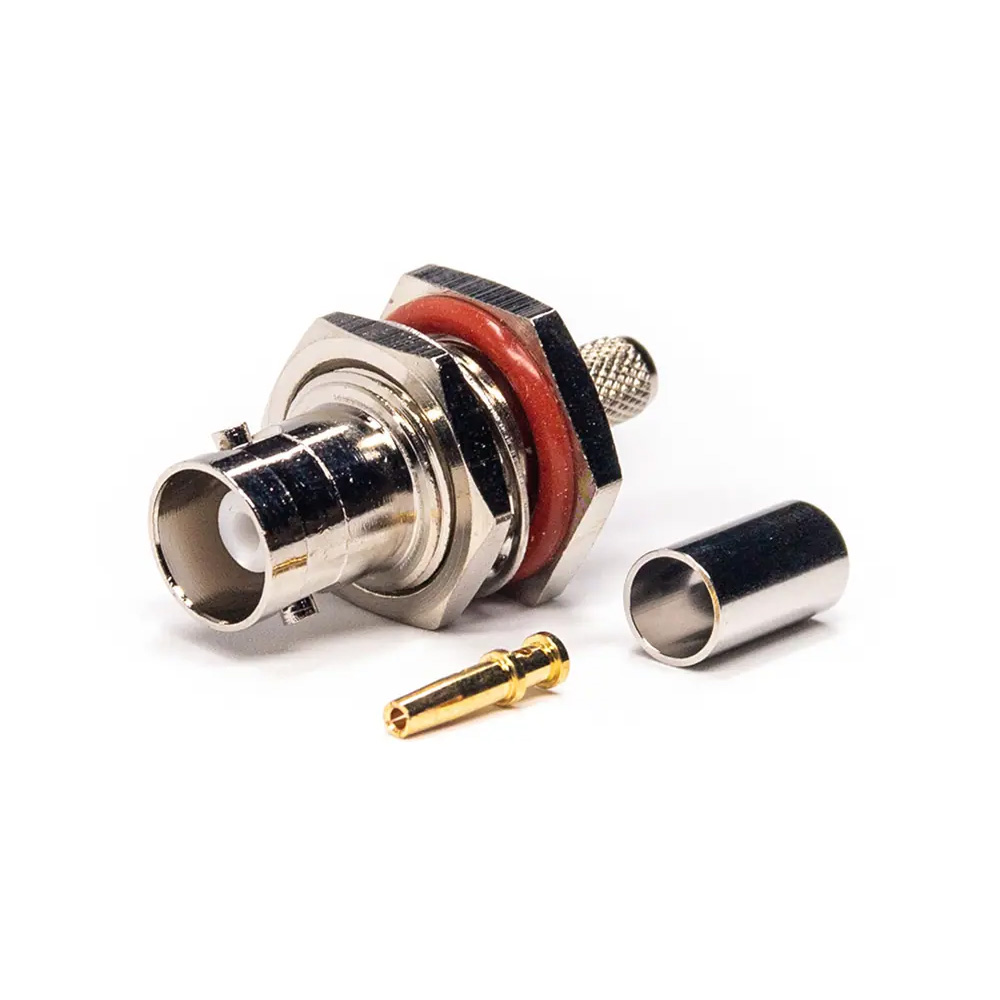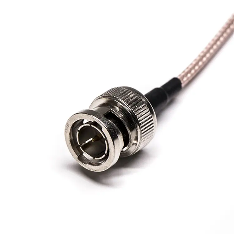
BNC Cable
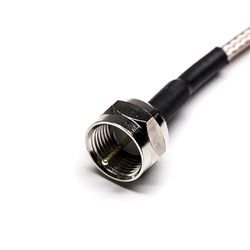
F Type Cable
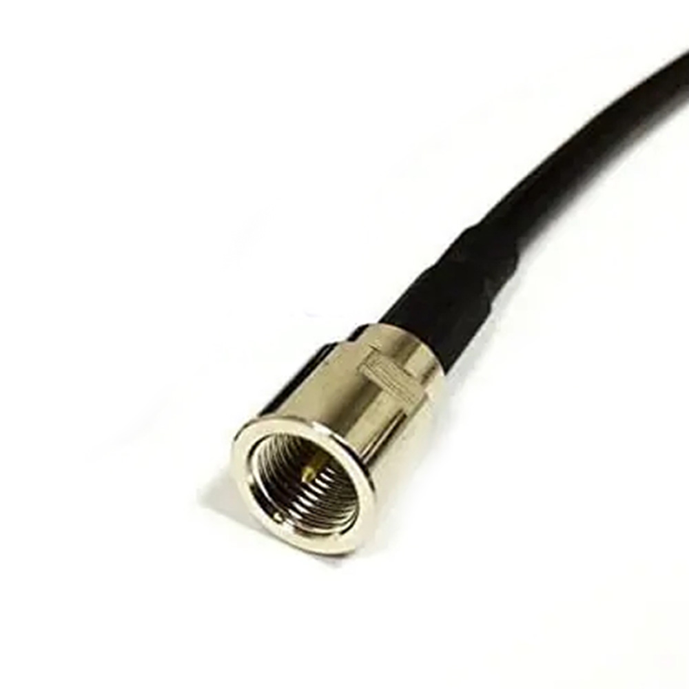
FME Cable
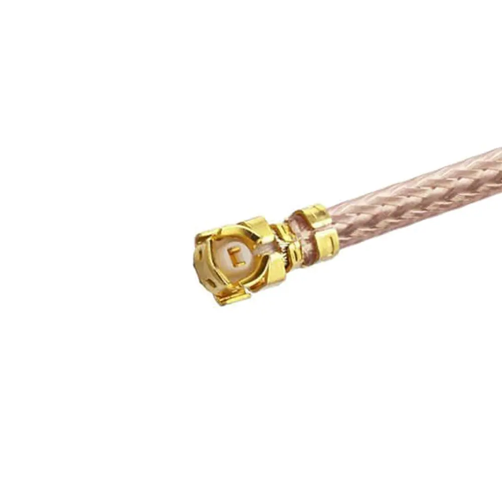
IPEX Cable
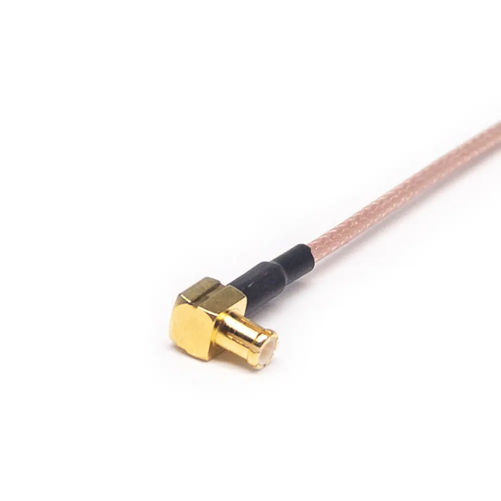
MCX Cable
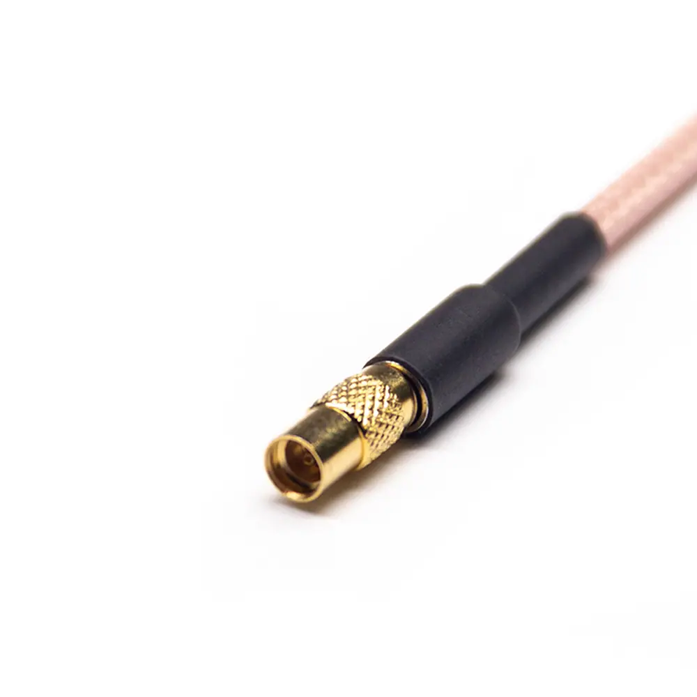
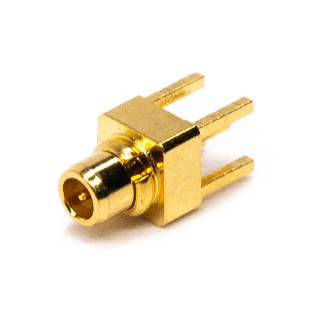
MMCX Cable
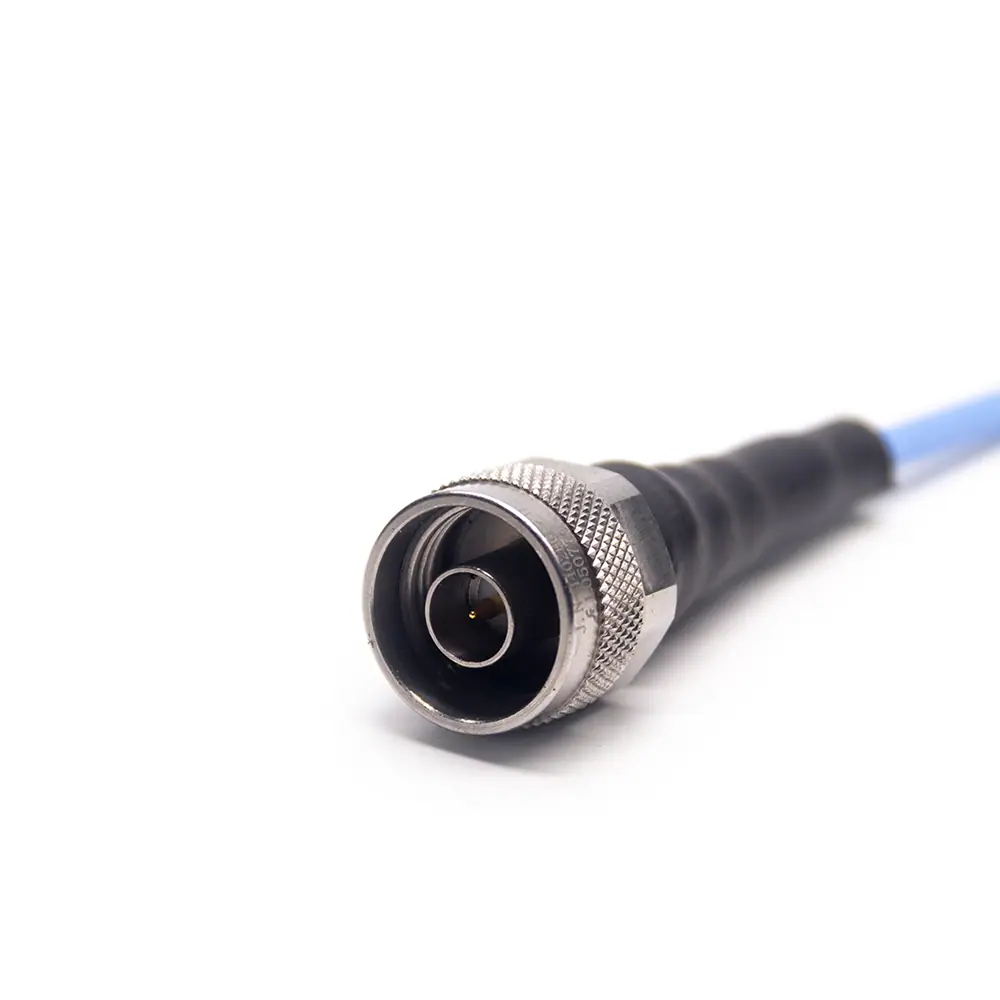
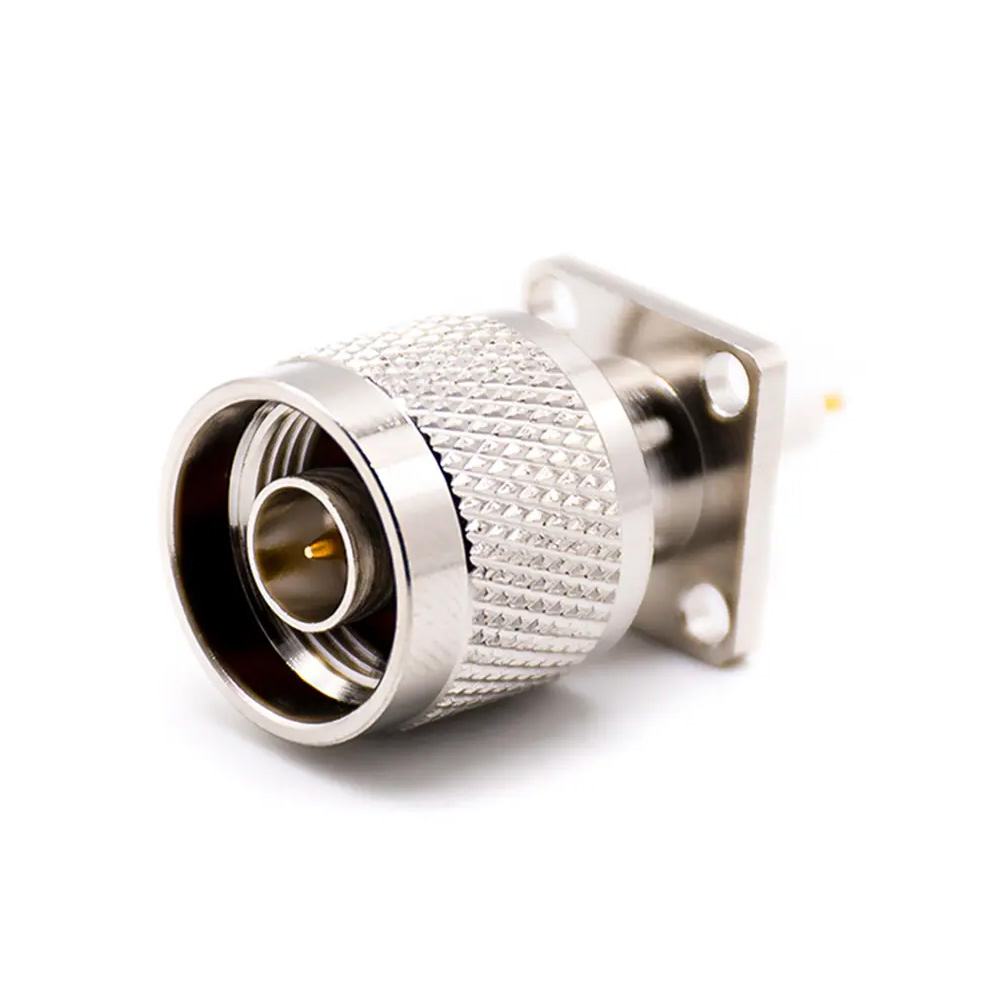
N Type Cable
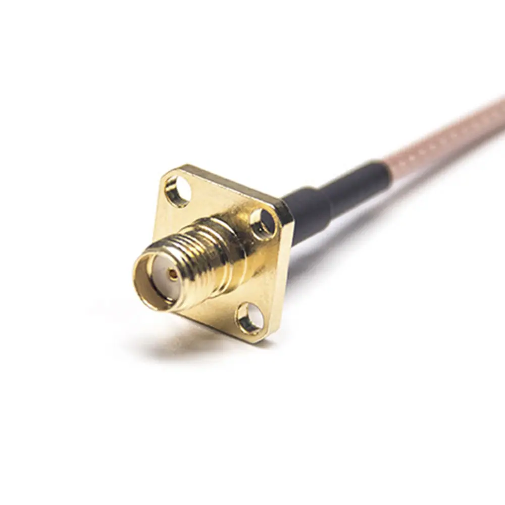
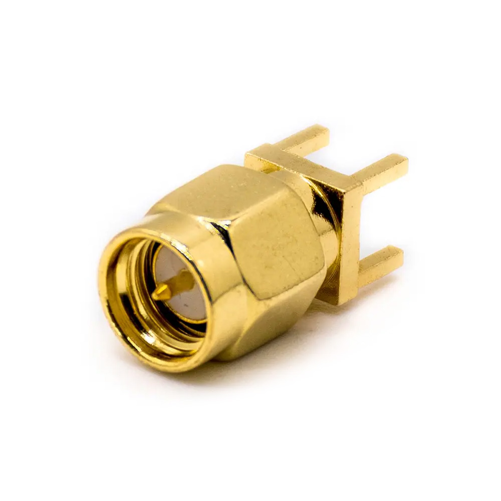
SMA Cable
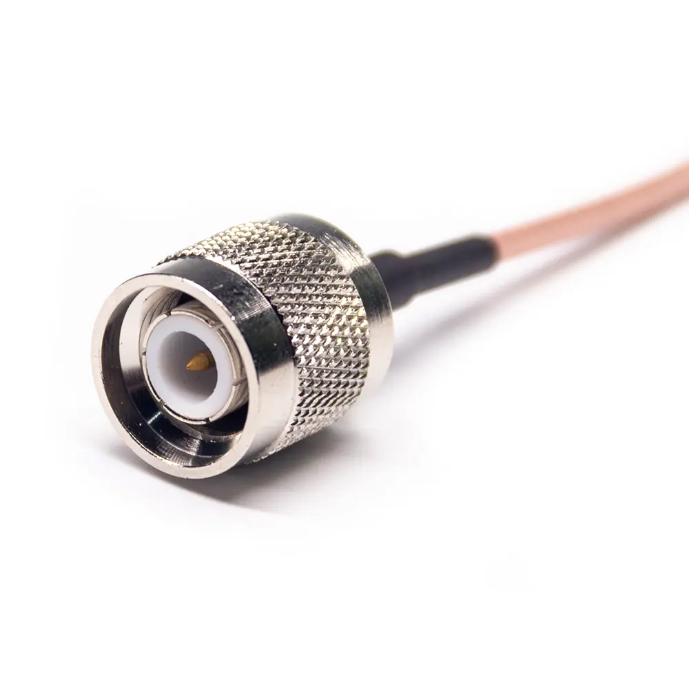
TNC Cable
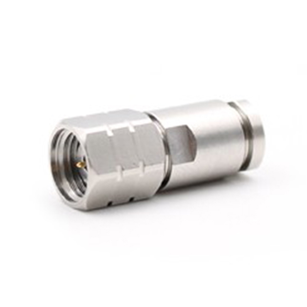
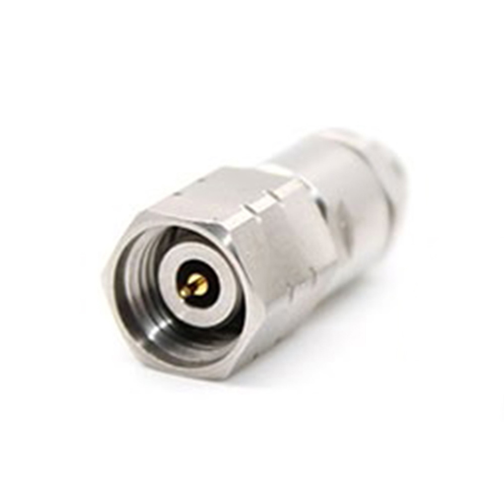
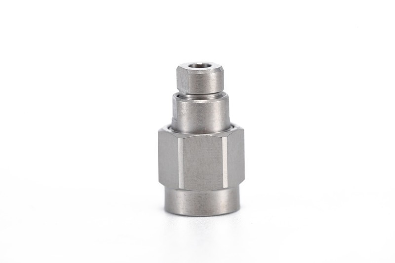
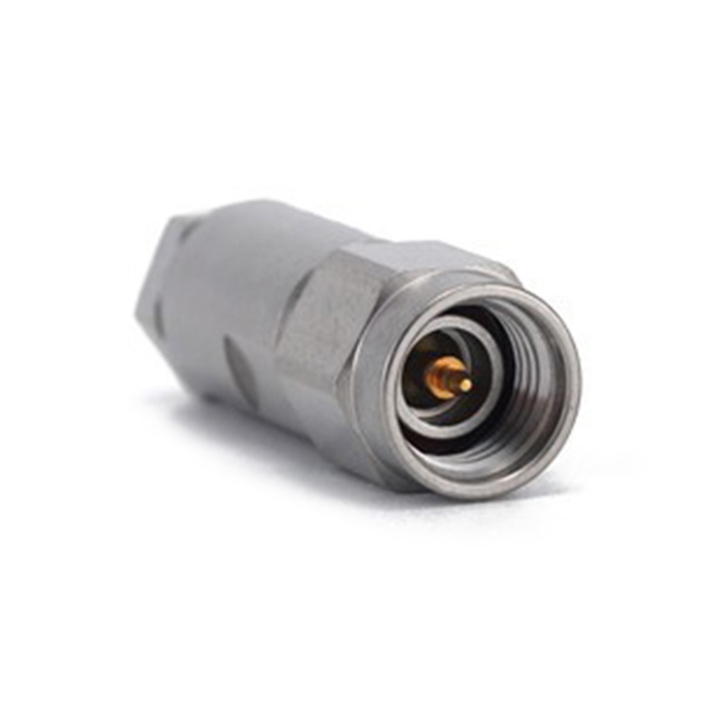
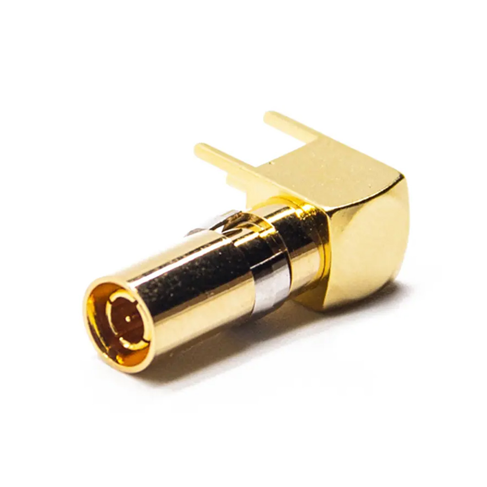
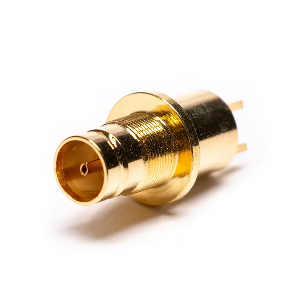
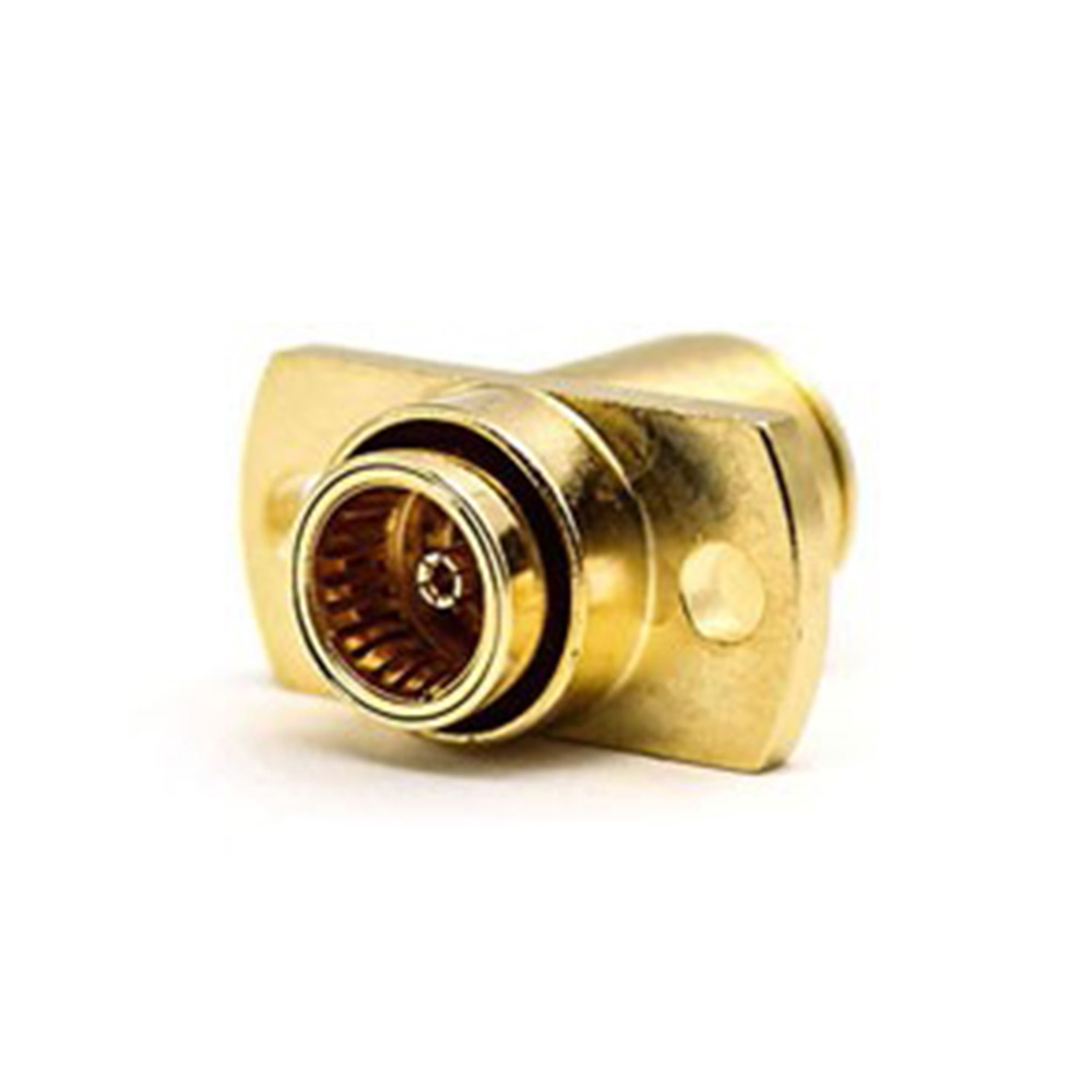
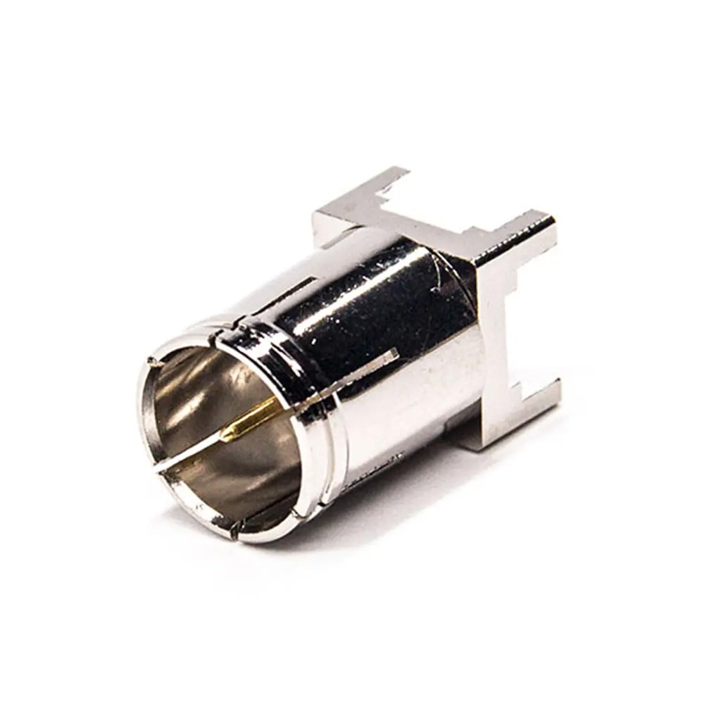
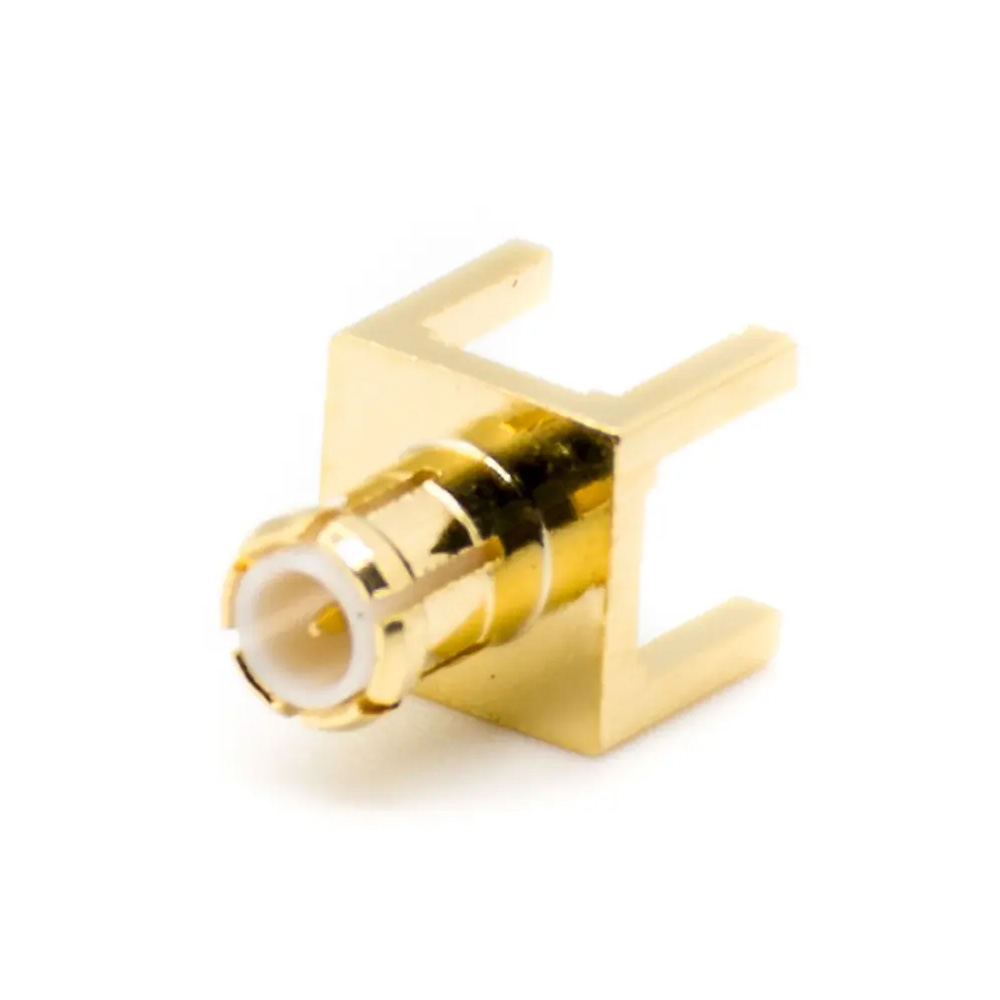
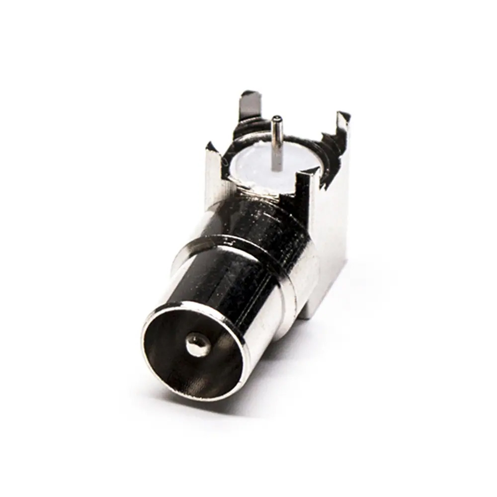
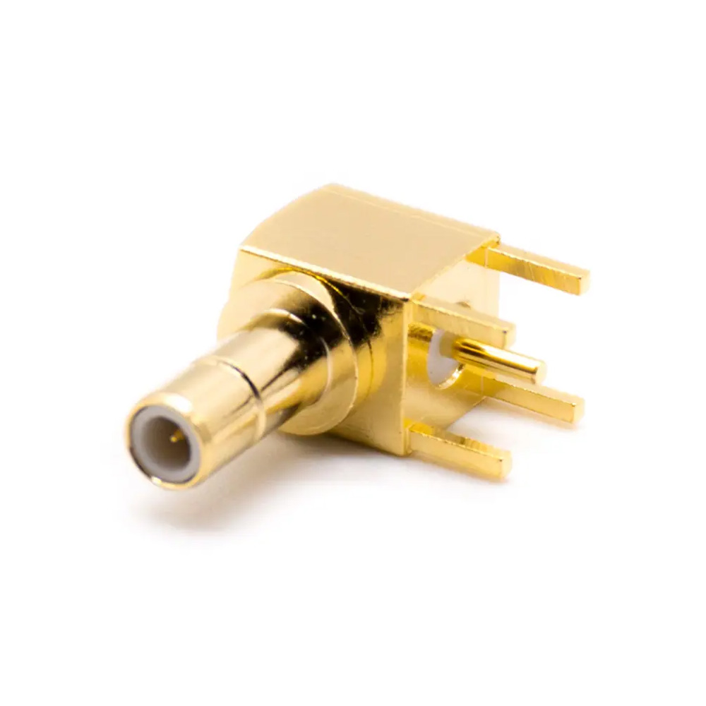
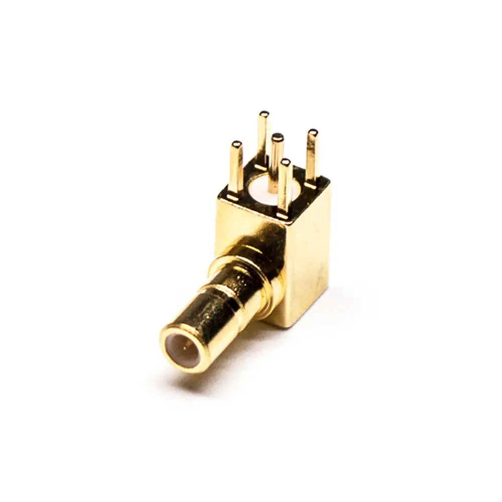
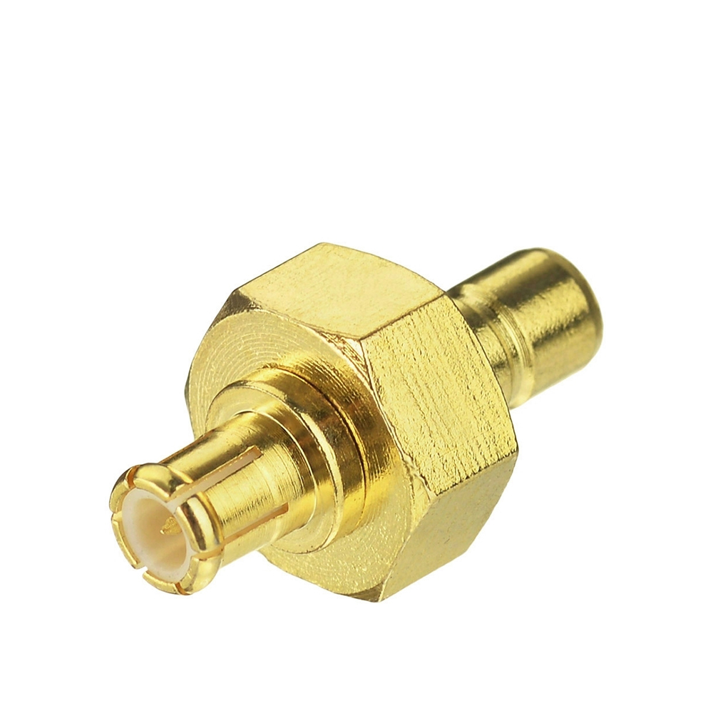
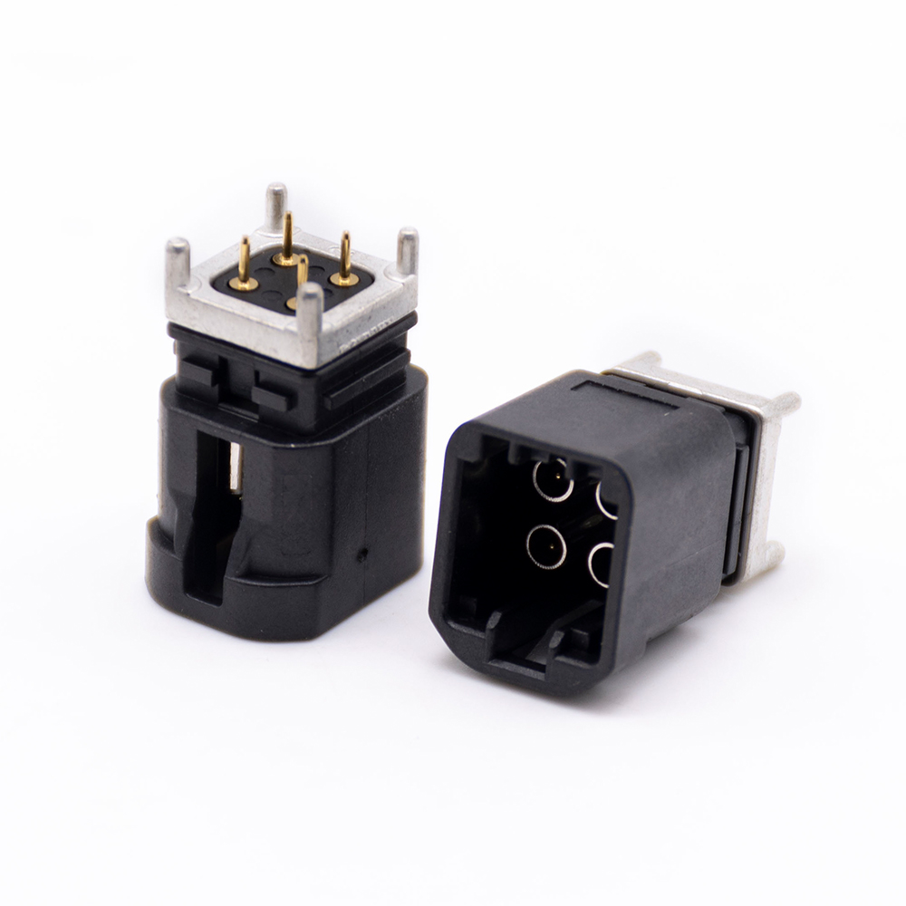
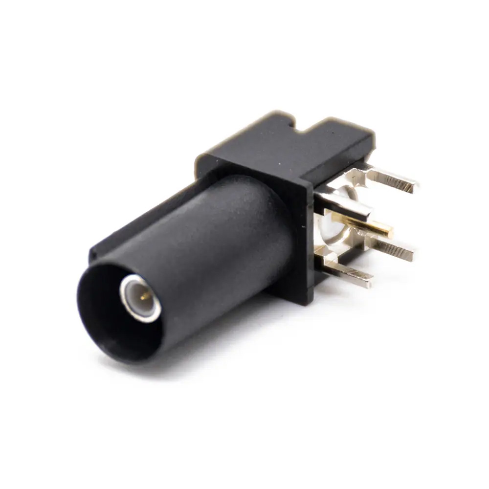
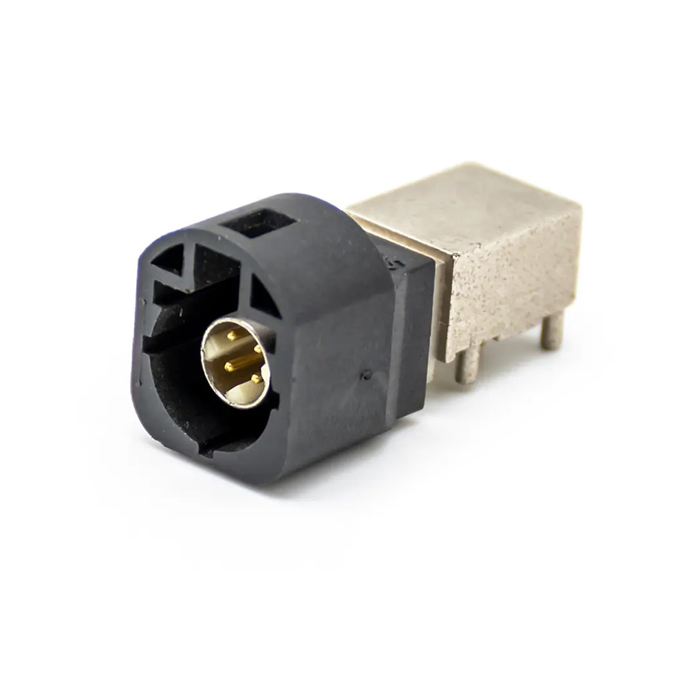
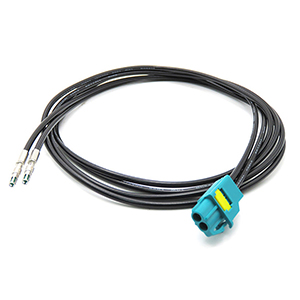
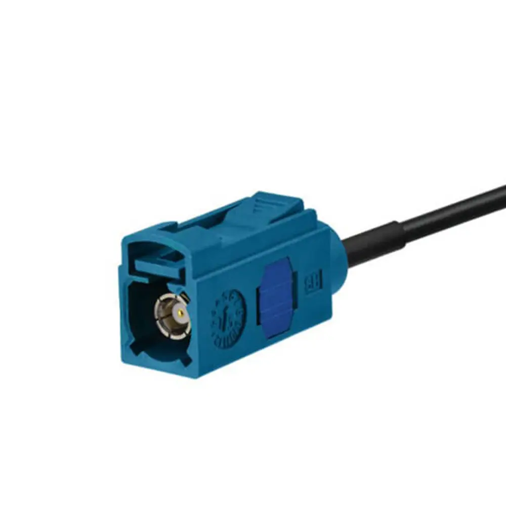
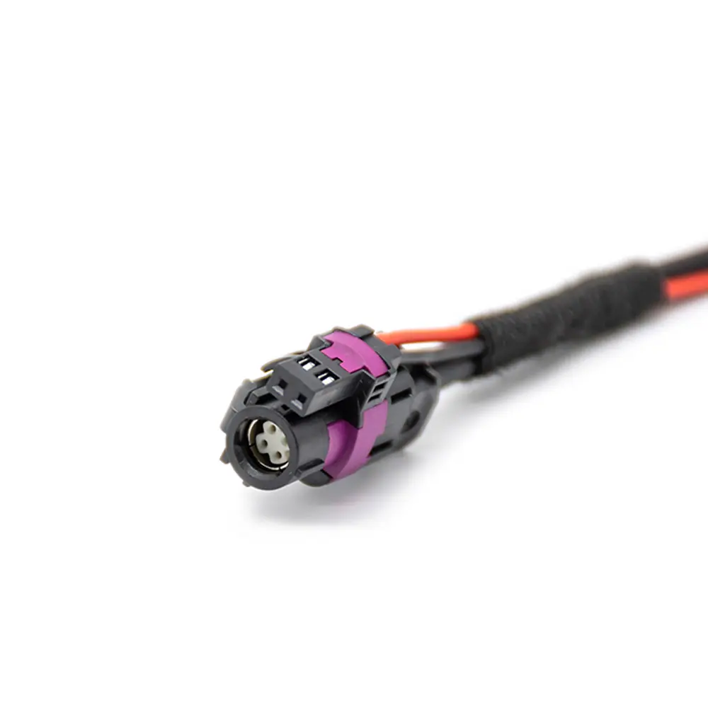
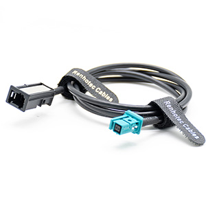
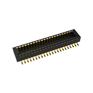
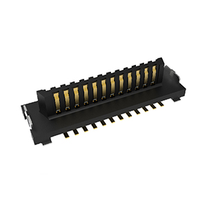
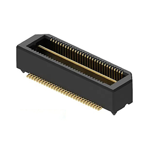
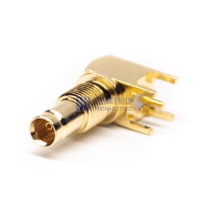
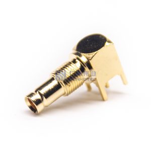
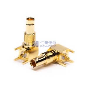
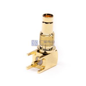
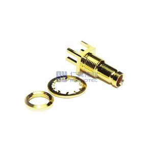
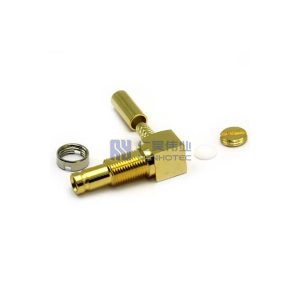
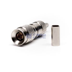
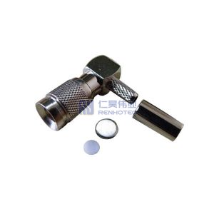
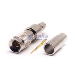
The 1.0-2.3 connector series was originally launched by the European Telecommunications Market in the 1990s. Compact design allows dense connector packaging, which is an ideal solution for applications with space constraints. It has 50 Ω and 75 Ω impedance for choice and is compatible with the most widely used cable sizes. The push/pull lock and release feature makes it really easy to use.

DIN 1.0-2.3 connectors are available to perform at 50 ohm with a maximum frequency of 10 GHz. As well as 75 ohm with a maximum frequency of 4 GHz. These performance specifications support high data rates for AES Audio, SD video, HD video, 3Gb/s video, and other high-density digital broadcast formats.


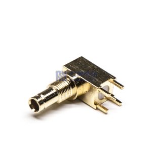
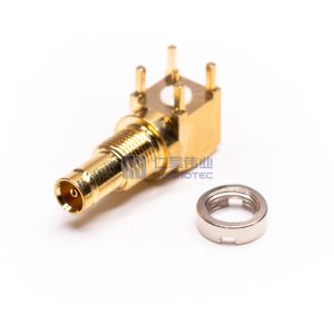
| RF Series | DIN 1.0/2.3 |
||
|---|---|---|---|
| Connector Type | Jack |
||
| Orientation | Right Angle |
||
| Contact Type | Female Pin |
||
| Contact Termination Style | Solder |
||
| Shield Termination | Solder |
||
| Mounting Type | Panel Mount |
||
| Mounting Feature | Through Hole |
||
| Fastening Type | Snap On |
||
| Number of Ports | 1 |
||
| Impedance | 75 ohm |
||
| Frequency Range | DC-3 GHz for 75 ohm, DC-10 GHz for 50 ohm |
||
| Shell Material | Copper Alloy |
||
| Shell Finish | Gold Plated |
||
| Insulator Material | PTFE |
||
| Contact Material | Brass |
||
| Contact Finish | Gold Plated |
||
| Temperature Range | -65°C to +165°C |
||
| Mating Durability | ≥ 500 Cycles |
||
| Insultation Resistance | 10000MΩ Min |
||
| Rated Voltage | 250 Volts RMS Max Continuous |
||
| Dielectric Withstanding Voltage | 750 VRMS Max |
||
| RF Series | DIN 1.0/2.3 |
Connector Type | Jack |
| Orientation | Right Angle |
Contact Type | Female Pin |
| Contact Termination Style | Solder |
Shield Termination | Solder |
| Mounting Type | Panel Mount |
Mounting Feature | Through Hole |
| Fastening Type | Snap On |
Number of Ports | 1 |
| Impedance | 75 ohm |
Frequency Range | DC-3 GHz for 75 ohm, DC-10 GHz for 50 ohm |
| Shell Material | Copper Alloy |
Shell Finish | Gold Plated |
| Insulator Material | PTFE |
Contact Material | Brass |
| Contact Finish | Gold Plated |
Temperature Range | -65°C to +165°C |
| Mating Durability | ≥ 500 Cycles |
Insultation Resistance | 10000MΩ Min |
| Rated Voltage | 250 Volts RMS Max Continuous |
Dielectric Withstanding Voltage | 750 VRMS Max |
| RF Series | DIN 1.0/2.3 |
|---|---|
| Connector Type | Jack |
| Orientation | Right Angle |
| Contact Type | Female Pin |
| Contact Termination Style | Solder |
| Shield Termination | Solder |
| Mounting Type | Panel Mount |
| Mounting Feature | Through Hole |
| Fastening Type | Snap On |
| Number of Ports | 1 |
| Impedance | 75 ohm |
| Frequency Range | DC-3 GHz for 75 ohm, DC-10 GHz for 50 ohm |
| Shell Material | Copper Alloy |
| Shell Finish | Gold Plated |
| Insulator Material | PTFE |
| Contact Material | Brass |
| Contact Finish | Gold Plated |
| Temperature Range | -65°C to +165°C |
| Mating Durability | ≥ 500 Cycles |
| Insultation Resistance | 10000MΩ Min |
| Rated Voltage | 250 Volts RMS Max Continuous |
| Dielectric Withstanding Voltage | 750 VRMS Max |